a. Adding Switches
Open the "Network" shape library:
Go to the left sidebar, click "Shapes", and enable the "Network" library.
Drag a switch icon onto the canvas.
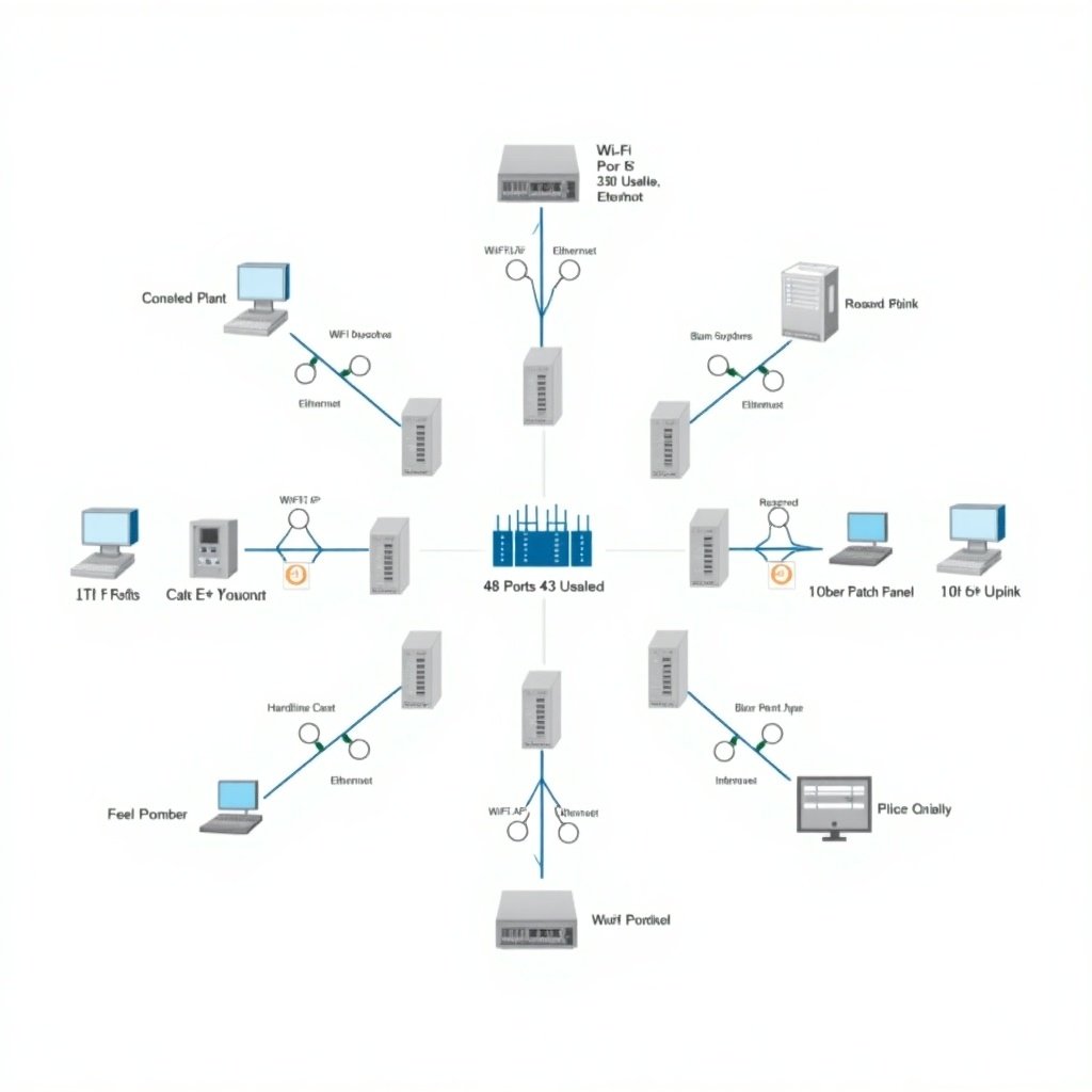
Label it as Cisco Catalyst MS390-48UX2.
Add text to show key details like "48 Ports (43 Usable, 30W PoE+)".
Duplicate the switch if needed to show multiple switches in the IT closet.
b. Adding Wi-Fi Access Points (APs)
Drag a wireless access point icon from the "Network" library.
Place it near the switches.
Label it as "Wi-Fi AP (PoE+ Powered)".
Connect the APs to the switches with lines to represent Ethernet cables.
Use straight lines for connections, and label them as "Cat6A Ethernet".
c. Adding Hardline Devices
Use icons like PCs, security cameras, or generic devices to represent hardline devices.
Label these as "Hardline Device (Ethernet)" and connect them to the switches.
d. Adding Fiber Patch Panels
Drag a rectangle or network symbol to represent the fiber patch panel.
Label it as "Fiber Patch Panel".
Show dual connections (uplinks) from the switches to the patch panel.
Use double lines labeled as "10 Gbps OM4 Fiber Uplink."
e. Connections and Ports
Use arrows or connectors to show how switches connect to APs, hardline devices, and the patch panel.
Label connections clearly, e.g., "10 Gbps Uplink," "30W PoE," or "Reserved for Scalability."
3. Organizing the Layout
Switch Placement:
Place switches in the center or bottom of the diagram.
APs and Devices:
Arrange APs and hardline devices around the switches.
Fiber Patch Panel:
Place the fiber patch panel at the top or side to show uplinks clearly, Network layout showing switches, Wi-Fi access points, and hardline devices. Central switch is Cisco Catalyst MS390-48UX2 with 48 ports. Wi-Fi APs are PoE+ powered. Hardline devices include PCs and security cameras. Fiber patch panel with dual 10 Gbps OM4 uplinks to the switches. Connections labeled clearly