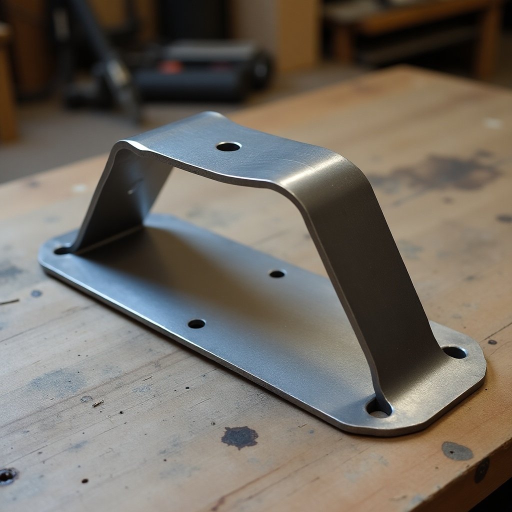
Suspension Control Arm Fabricated from Sheet Metal: Bending and Welding Techniques
Flux Prompt

AI Prompt

More Flux Images About Suspension control arm made of sheet metal

Suspension Control Arm Fabricated from Sheet Metal: Bending and Welding Techniques and Related Flux Artwork

Design features a stand with a screw mechanism to adjust the attached motor and paddle. A vessel is placed on a plate attached to the base, which has an LCD display showing measurement values.
G

Flux AI

Advanced Laboratory Measurement Device with Motorized Paddle and LCD Display

This image is a technical drawing showing a cylindrical stainless steel part. It features various measurements indicating its dimensions. The diameter at the top is 24 mm, while another part has a diameter of approximately 1.5875 mm. The drawing includes a thread specification of 1/2" 14 NPT and indicates the inner diameter as 18 mm. The total length of the part is noted as 200 mm. Clear annotations help in understanding the dimensions and specifications of the component.
S

Flux AI Image

Technical Drawing of a Cylindrical Stainless Steel Component with Thread Specifications and Dimensions

Carton corrugated sleeve box without lid shown. Box dimensions are 1200 mm x 600 mm x 150 mm. Thickness of cardboard is 2 mm.
A

FLUX.1-dev AI

Durable Corrugated Cardboard Sleeve Box – Dimensions 1200mm x 600mm x 150mm

The image presents a technical drawing of a mechanical component. It appears to have a cylindrical shape on top of a rectangular base. The dimensions are clearly marked, with various measurements indicated in millimeters. The drawing includes features such as a slot and a circular protrusion, along with dimensional indications for clarity. This could be part of a larger assembly or a specific machine part, showcasing precision engineering.
4 images
M

Flux AI Image

Technical Drawing of a Precision Mechanical Component

The image depicts a mechanical assembly of a fork lift shaft with two bearings situated at either end. It features two lifting sprockets designed to facilitate movement. Additionally, there is a driven sprocket which is powered by a motor. The illustration emphasizes the intricate details of each component in the assembly. Each element is clearly defined, providing an informative view for those studying mechanical design or engineering.
B

Flux AI Image Generator

Fork Lift Shaft Assembly with Bearings and Sprockets for Mechanical Engineering

Technical illustration drawing of a holder designed for four 250 ml coffee cups. Dimensions provided for length of 28.0 and width of 12.0 while height is 20.05. Frame supports two cups on each side, with detailed measurements shown.
I

Flux AI

Detailed Technical Illustration of Coffee Cup Holder for Four 250 ml Cups with Dimensions

A woman is preparing to lift a barbell in a gym setting.
3 images

FLUX dev AI

Focused Strength

Technical drawing of a mechanical component. Cylindrical shape on a rectangular base. Dimensions marked in millimeters. Includes slot and circular protrusion. Notches along the rectangular section. Details height of 30 units and width of 50 units. Side view captures depth and height with protruding notches. Serves as a reference for engineering and architectural projects.
A

FLUX.1-dev Image

Technical Drawing of Mechanical Component with Detailed Dimensions for Engineering and Architectural Reference

This image shows a technical drawing of a mechanical part designed in 3D. The component appears to be a bracket with multiple connection points and curved sections. Key dimensions are marked, indicating various radii and diameters, such as R24, R22, and several holes of different sizes. The illustration also specifies the distance between features and the overall length and height of the part. The visual style is clean, with a light blue color and clear annotations, typical for engineering schematics.
W

Flux AI Image

Detailed Technical Drawing of a 3D Mechanical Bracket with Connection Points and Dimensions

Create a detailed technical drawing of a mechanical component showing a base plate with rounded ends. Include a cylindrical structure with a diameter of 60 mm and a height of 60 mm on one end. Add a slot in the center of the base connecting the cylinder to a rectangular block. Label dimensions clearly.
A

FLUX.1-dev AI

Detailed Technical Drawing of a Mechanical Component with Dimensions and Features

This image features a measuring tape that is partially rolled out, displaying clear markings that indicate measurements in millimeters. The tape prominently shows the numbers from 1 to 5, with precise increments, making it ideal for measuring objects accurately. The lighting is soft, ensuring that the details on the tape are well-defined and easy to read. The color palette includes silver, black, and white, creating a clean and professional appearance. This image could be used in various contexts, such as construction guides or DIY project tutorials, emphasizing the importance of accurate measurements.
G

Flux Image Generator

2500 mm Line Measuring Tape with Millimeter Increment - Precision Measurement Tool

Design showcases a mechanical apparatus. Features a stand with a screw mechanism. Contains a motor attached to a paddle. A wooden base supports a glass vessel with a cap. The lower part displays numerical readings.
R

Flux AI

Innovative Mechanical Apparatus for Laboratory Use with Glass Vessel and Display