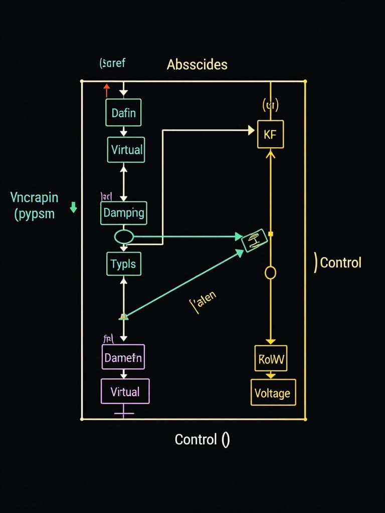
A schematic diagram for a proposed study on Designing and Implementing Virtual Synchronous Generator (VSG) Control System for Power Electronic Inverters Interfaced with Energy Storage Systems. This diagram is expected to clearly indicate two different interconnected computers that operates plan of inverters that are equipped with the VSG control capable of replicating the properties of a synchronous generator, providing virtual inertia and damping control to maintain voltage stability and frequency control consisting of 12V, 100W inverters. The design include the reference voltage (Vref), the reference frequency (fref), the gains of the virtual inertia control (Ki), the damping control (Kd), the voltage measurement (Kv), the frequency measurement (Kf), and the active control (Kcontrol). The actual voltage (V) and frequency (f) are measured and compared with the reference values to generate the control signals. YOU ARE EXPECTED TO COLORFULLY REDRAW THIS PLAN AND LABEL IT CLEARLY COMPONENTS BY COMPONENTS lines of code on a dark screen background, Schematic diagram for study on designing VSG control system for inverters interfaced with energy storage systems. Show interconnected computers and inverter control properties. Include reference voltage and frequency. Highlight gains for virtual inertia and damping. Illustrate measurements for voltage and frequency. Use a colorful dark screen background

