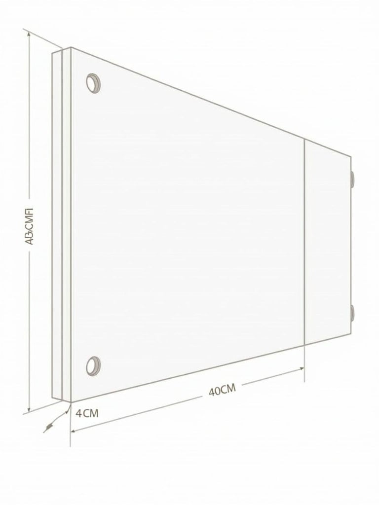
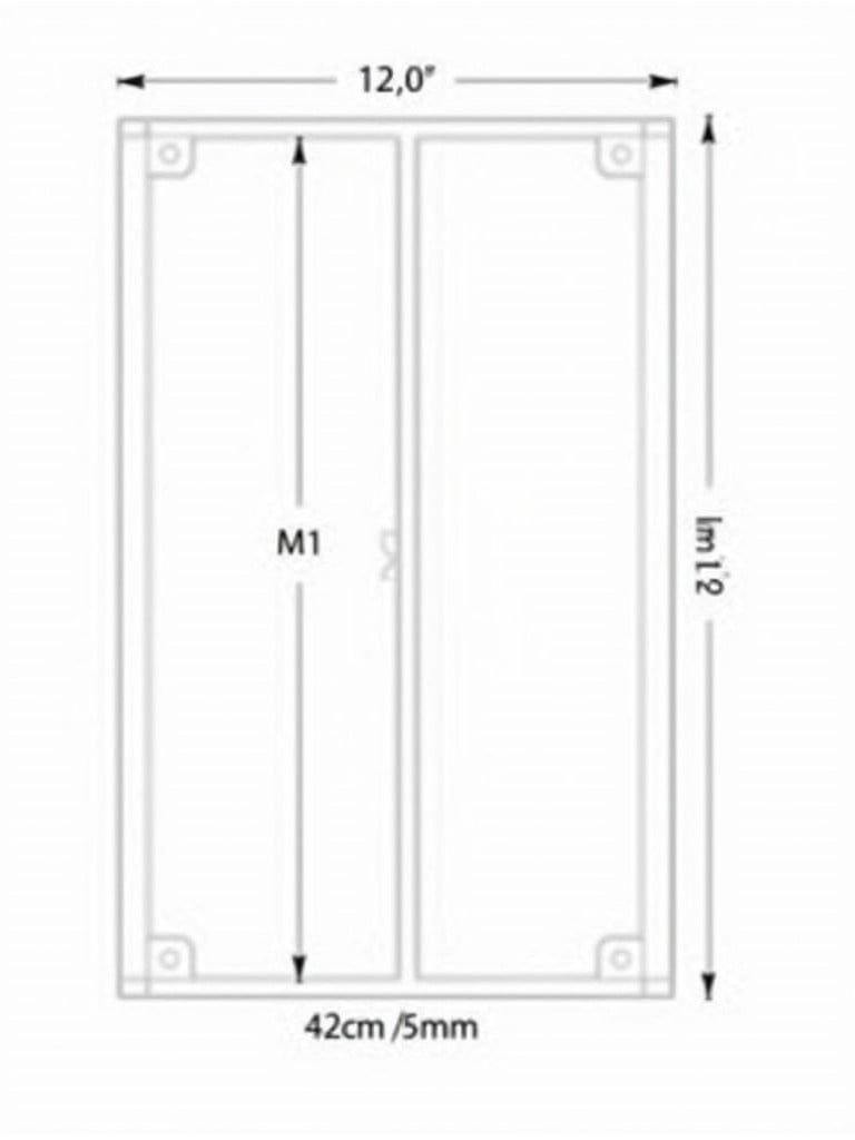
Technical Drawing of Dual-Sided E-Paper Departure Board Dimensions and Features

S
Generated by FLUX.1-dev
G
Image Size: 768 x 1024
Flux AI Model: FLUX.1-dev
Generator: Portrait 3:4
Flux Prompt
AI Prompt

K
Generated by FLUX.1-dev
G
Image Size: 768 x 1024
Flux AI Model: FLUX.1-dev
Generator: Portrait 3:4
AI Prompt
More Flux Images About Technical drawing of a dual-sided e-paper departure board
Technical Drawing of Dual-Sided E-Paper Departure Board Dimensions and Features and Related Flux Artwork
cross-section LED screen
dimensions of LED display
p10 LED screen
two-dimensional cabinet view
manufacturing technical illustration
LED screen architecture
technical drawing
circuit board close-up
College Programs
creative lighting
lighting design
electronic display design
cross-section drawing
LED display design
outdoor LED screen
light-emitting diode technology
screen cabinet specifications
digital advertising display
2D technical drawing
visual technology representation
design illustration
dimensions
isometric view
manufacturing design
orthographic projection
metric units
engineering education
technical illustration
component dimensions
orthographic views
mechanical design
prototyping reference
detailed measurements
Product Design
manufacturing
Prototyping
Orthographic view
isometric sketch
technical dimensions
component design
manufacturing specifications
engineering sketch
metric measurements
isometric view suggestion
side view
Top view
front view
CAD drawing
metric dimensions
technical drawing
design specifications
Engineering
design sketch
technical specifications
mechanical component design
CAD design
engineering standards
mechanical engineering
technical diagram
component blueprint
CAD
design sketches
product engineering
dimensioning
technical illustration
blueprint
technical drawing
Product Design
Mechanical parts
engineering design
manufacturing specifications
3rd angle projection
mechanical part analysis
Technical drawings
mechanical components
CAD drawings
orthographic projection
dimensional drawing
engineering documentation
engineering diagrams
engineering analysis
front view
design specifications
component dimensions
profile view
Profile view drawing
Manufacturing blueprints
Dimensional analysis
symmetrical design
Front view drawing
design and prototyping
component profile view
dimensions and symmetry
technical specifications
industrial design
dual-sided e-paper
departure board technical drawing
electronic display design
e-paper panel dimensions
landscape format drawing
technical specifications
M10 drilling holes
installation guide electronic board
housing dimensions
product visualization
wooden siding
architectural drawing
e-paper departure board
digital display technology
landscape format design
electronic signage
product specifications
technical illustration
technical drawing
dual-sided display
dimension annotations
Technical drawing of a dual-sided e-paper departure board


