Detailed Technical Drawings of Mechanical Parts for Engineering and Manufacturing Analysis
Flux Prompt

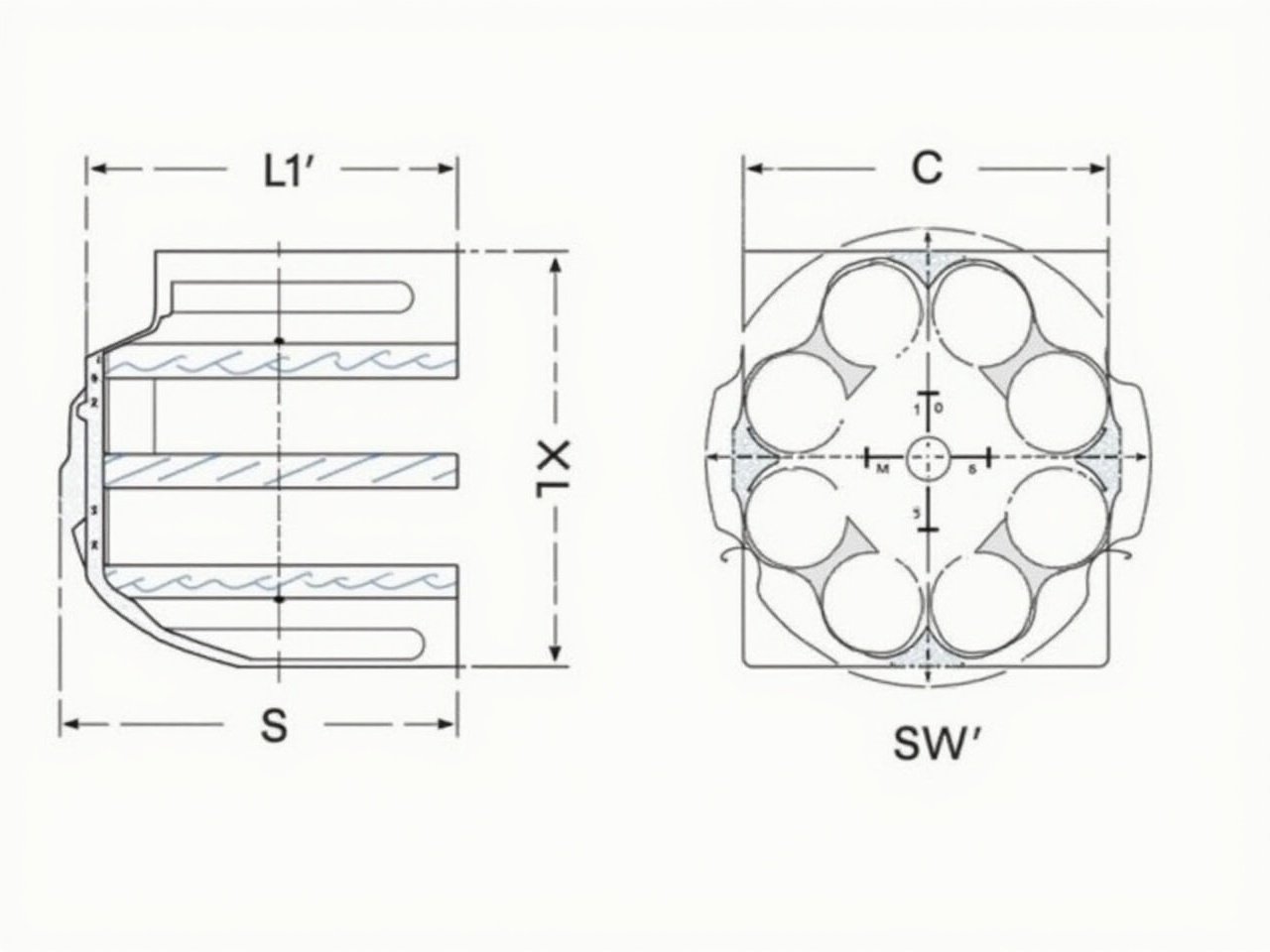
More Flux Images About Two technical drawings representing mechanical parts

Detailed Technical Drawings of Mechanical Parts for Engineering and Manufacturing Analysis and Related Flux Artwork

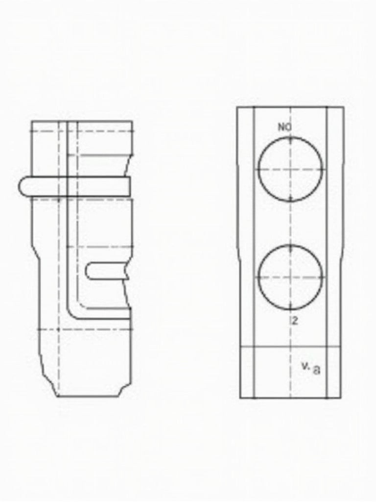
The image presents a technical drawing of a mechanical component. It appears to have a cylindrical shape on top of a rectangular base. The dimensions are clearly marked, with various measurements indicated in millimeters. The drawing includes features such as a slot and a circular protrusion, along with dimensional indications for clarity. This could be part of a larger assembly or a specific machine part, showcasing precision engineering.
5 images
M

FLUX dev AI

Technical Drawing of a Precision Mechanical Component

This image shows a technical drawing of a mechanical part designed in 3D. The component appears to be a bracket with multiple connection points and curved sections. Key dimensions are marked, indicating various radii and diameters, such as R24, R22, and several holes of different sizes. The illustration also specifies the distance between features and the overall length and height of the part. The visual style is clean, with a light blue color and clear annotations, typical for engineering schematics.
W

Flux AI Image Generator

Detailed Technical Drawing of a 3D Mechanical Bracket with Connection Points and Dimensions

The image presents a technical drawing of a mechanical component. It features a cylindrical shape atop a rectangular base with clearly marked dimensions in millimeters. The design includes a slot and a circular protrusion, highlighting precision in engineering. Notches are detailed along the rectangular section, and the front view shows its height of 30 units and width of 50 units. The side view captures the depth and height while emphasizing the protruding notches, making it a reliable reference for engineering and architectural projects.
p

Flux AI Image

Precision Mechanical Component Technical Drawing with Dimensions and Notches

Technical drawing of a mechanical component. Cylindrical shape on a rectangular base. Dimensions marked in millimeters. Includes slot and circular protrusion. Notches along the rectangular section. Details height of 30 units and width of 50 units. Side view captures depth and height with protruding notches. Serves as a reference for engineering and architectural projects.
A

FLUX dev AI

Technical Drawing of Mechanical Component with Detailed Dimensions for Engineering and Architectural Reference

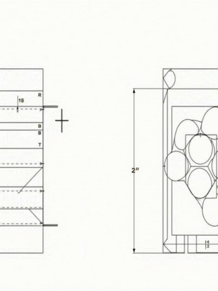
Engineering drawing with orthographic views in 3rd angle projection. Three views shown: front view, top view, side view. Contains various dimensions in metric units with key features including circles and angles. Section for sketching isometric view. Detailed measurements critical for manufacturing.
2 images
D

Flux AI Image Generator

Technical Engineering Drawing with Orthographic Views and Dimensions in Metric Units

Create a detailed technical drawing of a mechanical component showing a base plate with rounded ends. Include a cylindrical structure with a diameter of 60 mm and a height of 60 mm on one end. Add a slot in the center of the base connecting the cylinder to a rectangular block. Label dimensions clearly.
A

Flux AI Image Generator

Detailed Technical Drawing of a Mechanical Component with Dimensions and Features

This image showcases an engineering drawing with orthographic views, specifically in 3rd angle projection. The drawing contains three distinct views of a component: a front view, top view, and side view, all labeled with various dimensions in metric units. Key features include circles, angles, and additional notations for radii and diameters. There is a section marked 'Sketch isometric here,' suggesting a task for the viewer to provide an isometric view of the given design. The design includes detailed measurements such as lengths, widths, radii, and diameters, which are crucial for manufacturing or prototyping processes.
11 images
n

Flux AI

Engineering Drawing with Orthographic Views in 3rd Angle Projection for Manufacturing

Generate a side view blueprint drawing of the weapons shown. The drawing should clearly depict the details of both guns from a lateral perspective. Use clean lines and include measurements and labels for various components. Ensure that the finish and texture are represented accurately in a schematic style. Add a neutral background to enhance the clarity of the drawing.
2 images
a

FLUX.1-dev Image

Detailed Side View Blueprint Drawing of Firearms with Measurements and Labels

Engineering drawing features orthographic views. Displays dimensions in metric units. Highlights geometric features like circles and angles. Shows notations for radii and diameters. Includes section for isometric sketch. Provides detailed measurements for manufacturing. Essential for engineers and designers.
D

FLUX.1-dev Image

Detailed Engineering Drawing with Orthographic Views and Precise Dimensions

3rd angle projection showing a square with a hole of 25 radius. Dimensions are labeled around the square. The drawing is precise and technical in nature.
n

Flux AI

Technical Drawing: 3rd Angle Projection of a Square with a 25 Radius Hole

The image depicts a mechanical assembly of a fork lift shaft with two bearings situated at either end. It features two lifting sprockets designed to facilitate movement. Additionally, there is a driven sprocket which is powered by a motor. The illustration emphasizes the intricate details of each component in the assembly. Each element is clearly defined, providing an informative view for those studying mechanical design or engineering.
B

FLUX.1-pro AI

Fork Lift Shaft Assembly with Bearings and Sprockets for Mechanical Engineering

Technical drawing of a dual-sided e-paper departure board. E-paper panel is 13 inches integrated into a housing. Housing dimensions are 42 cm x 40 cm x 10 cm. Landscape format with two M10 drilling holes on the left side. Drawing shows front perspective with size annotations.
D

FLUX dev AI

Technical Drawing of Dual-Sided E-Paper Departure Board with Dimensions and Drilling Holes