Precision Mechanical Component Technical Drawing with Dimensions and Notches
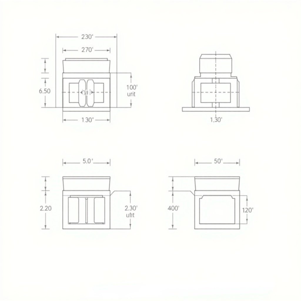
The image presents a technical drawing of a mechanical component. It features a cylindrical shape atop a rectangular base with clearly marked dimensions in millimeters. The design includes a slot and a circular protrusion, highlighting precision in engineering. Notches are detailed along the rectangular section, and the front view shows its height of 30 units and width of 50 units. The side view captures the depth and height while emphasizing the protruding notches, making it a reliable reference for engineering and architectural projects.
p

Generated by FLUX.1-dev

G

Flux Prompt

AI Prompt

More Flux Images About A mechanical component technical drawing

Precision Mechanical Component Technical Drawing with Dimensions and Notches and Related Flux Artwork

The image presents a technical drawing of a mechanical component. It appears to have a cylindrical shape on top of a rectangular base. The dimensions are clearly marked, with various measurements indicated in millimeters. The drawing includes features such as a slot and a circular protrusion, along with dimensional indications for clarity. This could be part of a larger assembly or a specific machine part, showcasing precision engineering.
M

Flux AI Image Generator

Technical Drawing of a Precision Mechanical Component

The image presents a technical drawing featuring a fillet with a radius of 3/4 inches. It includes precise measurements for various dimensions, including a height of 3.5 inches and width of 7 inches. The fillet is illustrated with a 37-degree angle, contributing to the drawing's overall design. The drawing is detailed, ensuring accuracy for engineering purposes. This schematic would be valuable in manufacturing or architectural contexts.
A

FLUX.1-pro Image

Technical Drawing of a Fillet with Dimensions and Radius Specifications

This image showcases an engineering drawing with orthographic views, specifically in 3rd angle projection. The drawing contains three distinct views of a component: a front view, top view, and side view, all labeled with various dimensions in metric units. Key features include circles, angles, and additional notations for radii and diameters. There is a section marked 'Sketch isometric here,' suggesting a task for the viewer to provide an isometric view of the given design. The design includes detailed measurements such as lengths, widths, radii, and diameters, which are crucial for manufacturing or prototyping processes.
2 images
n

FLUX.1-dev AI

Engineering Drawing with Orthographic Views in 3rd Angle Projection for Manufacturing

A person is sketching a man on graph paper with a pencil.

Flux AI

Drawing in Progress

A person is drawing sketches on a piece of paper using a pencil on a wooden table.

FLUX.1-dev Image

Sketching Ideas

This technical drawing features a rectangular section detailed with notches. The front view illustrates a height of 30 units and a width of 50 units, clearly depicting 10x10 notches on either side. The top view shows the same width of 50 units and a depth that accounts for the notches. Additionally, the side view captures a height of 30 units and a depth of 50 units, emphasizing the notches as protruding features. This illustration serves as a precise representation for engineering and architectural projects, beneficial for ensuring accuracy in specifications.
4 images
A

Flux AI Image Generator

Technical Drawing of Rectangular Section with Notches for Engineering and Architectural Use

The image displays a technical drawing of a pentagonal pyramid with a base of 50 mm sides and an axis length of 70 mm. The base lies on the horizontal plane, with one of the base edges oriented perpendicular to the vertical plane. A section plane is shown, which is perpendicular to the vertical plane and inclined at 40 degrees to the horizontal plane, bisecting the axis of the pyramid. The various views represent the front view, sectional top view, sectional side view, and the true shape of the section. This drawing illustrates the complex geometry involved in three-dimensional shapes in a two-dimensional format.
S

FLUX.1-dev Image

Pentagonal Pyramid Technical Drawing with Section Plane at 40° to H.P.

A person is sketching technical drawings and diagrams in a notebook with a black pen on a wooden table.

Flux Image Generator

Sketching Ideas

A hand holding a pen is sketching a design on paper with line art details.
2 images
M

FLUX.1-pro Image

Design Sketching

A yellow pencil rests on a detailed engineering blueprint on a wooden desk.
3 images
The image displays a technical drawing of a pentagonal pyramid. It has a base with sides measuring 50 mm and an axis length of 70 mm. The base is positioned on the horizontal plane. One edge of the base is oriented perpendicularly to the vertical plane. A section plane is illustrated, which is perpendicular to the vertical plane and inclined at 40 degrees to the horizontal. This section plane bisects the pyramid's axis. The various views include the front view, sectional top view, sectional side view, and the true shape of the section, demonstrating complex geometry in a two-dimensional layout.
K

Flux AI Image

Technical Drawing of a Pentagonal Pyramid: Understanding Geometry and Sectional Views

The image depicts a simplified engineering sketch of a lathe machine, designed with clear lines and minimal detail. The lathe is shown from the side, highlighting its basic components such as the motor, chuck, and tool post. It captures the essential features necessary for understanding lathe operation without any realistic shading or colors. The outer edges are defined crisply to ensure clarity. Measurement tools like calipers and a micrometer hint at the precision aspect of machining while remaining part of the illustration. The overall style should reflect a 2D technical drawing used for educational purposes.
A

Flux Image Generator

Engineering Sketch of a Lathe Machine for Cylindrical Machining