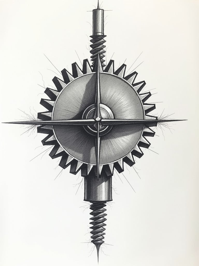
Realistic Illustration of Bevel Gear - Technical Drawing for Engineering Applications
Generated by FLUX.1-dev
Flux Prompt
AI Prompt
More Flux Images About A meticulously drawn bevel gear
Realistic Illustration of Bevel Gear - Technical Drawing for Engineering Applications and Related Flux Artwork
The image depicts a technical drawing of a bevel gear. The gear is represented in outline form. The gear design features a 30-degree angle for precise engineering applications.
Prompt:
The image shows a close-up view of multiple interlocking gears, meticulously crafted with a metallic finish.
Prompt:
A yellow pencil rests on a detailed engineering blueprint on a wooden desk.
Prompt:
The image presents a technical drawing of a mechanical component. It appears to have a cylindrical shape on top of a rectangular base. The dimensions are clearly marked, with various measurements indicated in millimeters. The drawing includes features such as a slot and a circular protrusion, along with dimensional indications for clarity. This could be part of a larger assembly or a specific machine part, showcasing precision engineering.
Prompt:
A close-up of a drill press machining a computer processor on a workbench.
The image presents a technical drawing of a mechanical component. It features a cylindrical shape atop a rectangular base with clearly marked dimensions in millimeters. The design includes a slot and a circular protrusion, highlighting precision in engineering. Notches are detailed along the rectangular section, and the front view shows its height of 30 units and width of 50 units. The side view captures the depth and height while emphasizing the protruding notches, making it a reliable reference for engineering and architectural projects.
Prompt:
Sketch depicts a V-shaped clamp block. Dimensions include 8M and 827me. Technical style showcases precise lines and angles. Background grid highlights measurement.
Prompt:
The image depicts a simplified engineering sketch of a lathe machine, designed with clear lines and minimal detail. The lathe is shown from the side, highlighting its basic components such as the motor, chuck, and tool post. It captures the essential features necessary for understanding lathe operation without any realistic shading or colors. The outer edges are defined crisply to ensure clarity. Measurement tools like calipers and a micrometer hint at the precision aspect of machining while remaining part of the illustration. The overall style should reflect a 2D technical drawing used for educational purposes.
Prompt:
The image displays two technical drawings, which appear to represent mechanical parts or components. The left drawing showcases a profile view with several dashed and solid lines that indicate different surfaces and contours of the part. There are horizontal lines suggesting layers or levels on the part shown. The right drawing presents a front view with circular shapes that may represent holes or recesses in the material. This drawing also includes dimensions and symmetry hints, indicated by the crosshair-like symbols. Overall, the drawings convey technical specifications relevant for manufacturing or engineering analysis.
Prompt:
The image displays two technical drawings representing mechanical components. The left drawing showcases a profile view with various lines indicating surfaces. The right drawing presents a front view with circular shapes that may represent holes. Dimensions are clearly marked in millimeters. Features include a slot and circular protrusion. Drawings convey technical specifications relevant for engineering.
Prompt:
A futuristic close-up of a glowing circuit board resembling a clock face.
Draw front view of sewing machine. Features vintage elements and details. includes various components like needle, wheel, and base. Emphasize mechanical design.