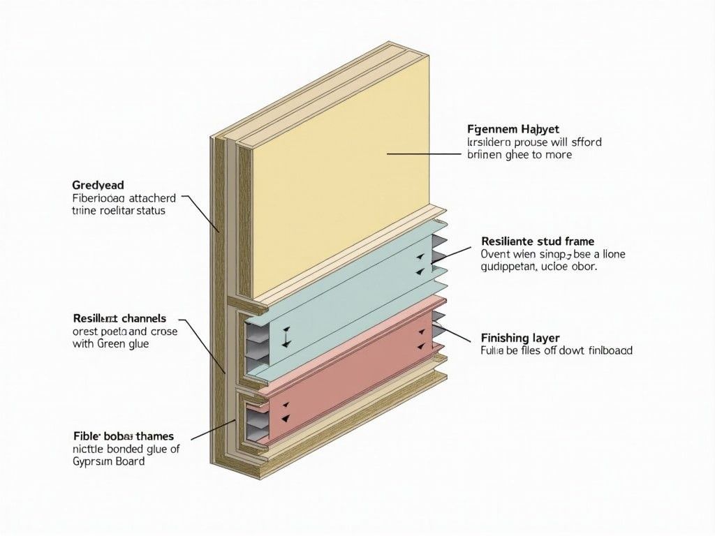
Simplified 2D Cross-Section Drawing of Soundproof Wall Construction

Flux Prompt

AI Prompt

More Flux Images About Wall cross-section detailing construction layers

Simplified 2D Cross-Section Drawing of Soundproof Wall Construction and Related Flux Artwork

This is a 2D cross-section drawing of a staggered stud wall designed for sound isolation. The drawing shows multiple layers starting from the inner portion, including staggered studs creating an air gap. Rockwool insulation fills the spaces between these studs. Next, there’s a secondary layer comprising 12.7 mm Fibreboard attached to 15.9 mm Gypsum Board, using Green Glue for enhanced damping. The outer layer features resilient channels affixed to the studs, topped with another layer of 12.7 mm fibreboard and 18 mm gypsum board. The drawing also illustrates joint sealants and wooden plates for airtightness. Lastly, all joints and edges are carefully sealed to ensure soundproofing efficacy.
S

FLUX.1-pro Image

2D Cross-Section Drawing of Staggered Stud Wall for Sound Isolation

This image features a 2D cross-section of a decoupled wall illustrated in a basic pencil drawing style. The foundational wall is depicted at the base with a distinct outline. Above the main wall, staggered studs are shown, creating an air gap filled with rockwool insulation for soundproofing properties. On the other side of the studs, two colored layers are represented: one is a vibrant yellow, and the other appears in a mild green hue, enhancing the visual interest of the structure. The overall design captures both the technical aspects and aesthetic considerations in wall design.
S

Flux AI

2D Cross-Section of a Decoupled Wall with Staggered Studs and Rockwool Insulation

This detailed drawing illustrates a 2D cross-section of a staggered stud wall aimed at sound isolation. The inner layers showcase staggered studs, which create an air gap and are filled with Rockwool insulation for enhanced sound absorption. A secondary layer includes 12.7 mm Fibreboard and 15.9 mm Gypsum Board, utilizing Green Glue for additional damping properties. The outer layer features resilient channels attached to the studs, providing further acoustic benefits. Additionally, another layer of 12.7 mm fibreboard and 18 mm gypsum board caps the structure. The drawing emphasizes joint sealants and wooden plates for airtightness, ensuring maximum soundproofing effectiveness. It depicts all edges and joints meticulously sealed for optimal performance.
w

FLUX.1-dev Image

Staggered Stud Wall Cross-section for Optimal Sound Isolation

This technical drawing represents a rectangular section with notches. The front view shows a height of 30 units and a width of 50 units, highlighting 10x10 notches on each side. The top view maintains the same width of 50 units and a depth that includes the notches. The side view reflects a height of 30 units and a depth of 50 units, showcasing the notches as protrusions. This illustration can be utilized in engineering and architectural contexts for precise representation of specifications.
A

FLUX pro Image Generator

Orthographic Technical Drawing of a Rectangular Section with Notches

The image is a detailed architectural section plan of a two-story building. It shows the layout of different rooms such as a kitchen, hall, WC, and storage areas. The plan includes measurements and annotations indicating different dimensions and components of the structure. Windows and doors are marked distinctly, providing a clear view of their placement. The diagram also highlights the staircase connecting the two floors, along with some interior furnishings like tables and cabinets.
J

FLUX pro AI

Detailed Architectural Section Plan of a Two-Story Building Layout with Kitchen, Hall, and Furnishings

This technical drawing features a rectangular section detailed with notches. The front view illustrates a height of 30 units and a width of 50 units, clearly depicting 10x10 notches on either side. The top view shows the same width of 50 units and a depth that accounts for the notches. Additionally, the side view captures a height of 30 units and a depth of 50 units, emphasizing the notches as protruding features. This illustration serves as a precise representation for engineering and architectural projects, beneficial for ensuring accuracy in specifications.
A

FLUX.1-dev AI

Technical Drawing of Rectangular Section with Notches for Engineering and Architectural Use

The image is a detailed architectural section plan of a two-story building. It showcases an open layout connecting multiple rooms, including a kitchen, hall, WC, and storage areas, each with different ceiling heights. The plan is annotated with precise measurements indicating dimensions and structural components. Large windows and doors are distinctly marked to highlight their placement, allowing natural light into the space. A staircase links the two floors, with furniture elements like tables and cabinets suggested in the diagram, emphasizing the open connection between rooms and the outside environment.
P

Flux AI Image

Detailed Architectural Section Plan of a Two-Story Building with Open Layout and Measured Spaces

A wooden cross is mounted on a wooden wall with dramatic lighting creating shadows.
3 images

FLUX.1-dev Image

Wooden Cross in Shadows

Convert this 3D model into a sectional drawing. Use varied line weights to show depth, with thicker lines for objects closer to the viewer and thinner lines for those further away. Highlight the details of the tables and cylindrical sections with precise line work. Ensure the walls and structural elements are clearly defined with appropriate hatch patterns. Maintain clear separation between different planes to enhance the sense of depth and spatial arrangement.
4 images
V

Flux AI Image Generator

Sectional Drawing Techniques: Showcasing Depth with Line Weights and Details

This is a layout plan of a complex or facility. It features various buildings labeled with their intended purposes, such as 'Private Residence', 'Gathering Hall', 'Education and Gallery', 'Animal Husbandry', and 'Admin'. The layout includes multiple lawns and parking areas, emphasizing green spaces alongside the structures. The roads and paths are marked, showing the connectivity between different sections of the complex. Contours or elevation lines indicate changes in the terrain. Overall, the plan appears to be organized and includes a variety of amenities for different functions.
N

FLUX.1-pro Image

Detailed Architectural Layout Plan of a Multi-Purpose Complex with Green Amenities

The image showcases a well-designed 4-floor building with a commercial shop on the ground floor and residential apartments on the upper floors. Each residential unit features balconies adorned with potted greenery, adding a touch of nature to the facade. Large glass windows provide ample light and create an inviting appearance. The ground floor shop area is designed to be accessible, encouraging foot traffic. The overall structure combines modern aesthetics with functional design, making it suitable for urban living.
R

FLUX.1-pro AI

Modern 4 Floor Building Elevation Design with Shop and Balconies

A series of bright blue pipes connected at right angles against a white wall.
3 images