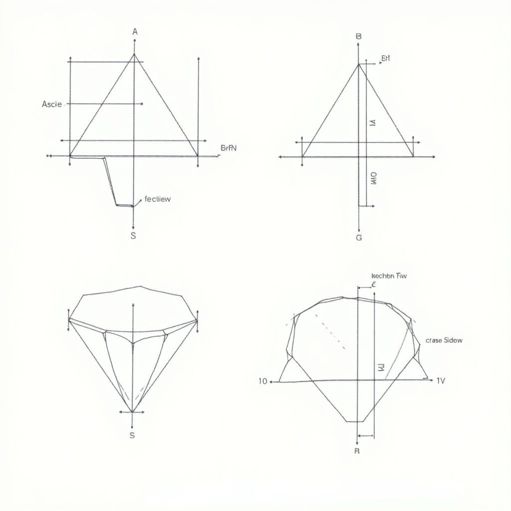
Technical Drawing of a Pentagonal Pyramid: Understanding Geometry and Sectional Views

Flux Prompt

AI Prompt

More Flux Images About Pentagonal pyramid technical drawing

Technical Drawing of a Pentagonal Pyramid: Understanding Geometry and Sectional Views and Related Flux Artwork

The image displays a technical drawing of a pentagonal pyramid with a base of 50 mm sides and an axis length of 70 mm. The base lies on the horizontal plane, with one of the base edges oriented perpendicular to the vertical plane. A section plane is shown, which is perpendicular to the vertical plane and inclined at 40 degrees to the horizontal plane, bisecting the axis of the pyramid. The various views represent the front view, sectional top view, sectional side view, and the true shape of the section. This drawing illustrates the complex geometry involved in three-dimensional shapes in a two-dimensional format.
S

FLUX.1-dev AI

Pentagonal Pyramid Technical Drawing with Section Plane at 40° to H.P.

This image showcases an engineering drawing with orthographic views, specifically in 3rd angle projection. The drawing contains three distinct views of a component: a front view, top view, and side view, all labeled with various dimensions in metric units. Key features include circles, angles, and additional notations for radii and diameters. There is a section marked 'Sketch isometric here,' suggesting a task for the viewer to provide an isometric view of the given design. The design includes detailed measurements such as lengths, widths, radii, and diameters, which are crucial for manufacturing or prototyping processes.
n

Flux AI Image Generator

Engineering Drawing with Orthographic Views in 3rd Angle Projection for Manufacturing

This technical drawing represents a rectangular section with notches. The front view shows a height of 30 units and a width of 50 units, highlighting 10x10 notches on each side. The top view maintains the same width of 50 units and a depth that includes the notches. The side view reflects a height of 30 units and a depth of 50 units, showcasing the notches as protrusions. This illustration can be utilized in engineering and architectural contexts for precise representation of specifications.
A

FLUX.1-pro AI

Orthographic Technical Drawing of a Rectangular Section with Notches

The image showcases a transparent outline of a rectangular box with dimensions indicated. The design emphasizes its length, width, and height, providing clear measurements in inches. The drawing is presented in an isometric perspective, making it easy to understand the 3D form of the box. Measurement lines and notes are highlighted in yellow against a gray background, ensuring clarity. This technical illustration is perfect for engineering or architectural purposes.
S

Flux Image Generator

First and Third Angle Projection Technical Drawing of a Rectangular Box

The image presents a technical drawing of a mechanical component. It appears to have a cylindrical shape on top of a rectangular base. The dimensions are clearly marked, with various measurements indicated in millimeters. The drawing includes features such as a slot and a circular protrusion, along with dimensional indications for clarity. This could be part of a larger assembly or a specific machine part, showcasing precision engineering.
M

FLUX dev AI

Technical Drawing of a Precision Mechanical Component

A close-up image of shiny golden pyramid shapes on a textured surface.
3 images

FLUX.1-dev AI

Golden Pyramid Patterns

A golden, metallic-textured triangle set against a smooth green background.

FLUX.1-dev AI

Golden Triangular Mystery

The image presents a technical drawing featuring a fillet with a radius of 3/4 inches. It includes precise measurements for various dimensions, including a height of 3.5 inches and width of 7 inches. The fillet is illustrated with a 37-degree angle, contributing to the drawing's overall design. The drawing is detailed, ensuring accuracy for engineering purposes. This schematic would be valuable in manufacturing or architectural contexts.
A

FLUX.1-pro Image

Technical Drawing of a Fillet with Dimensions and Radius Specifications

This technical drawing features a rectangular section detailed with notches. The front view illustrates a height of 30 units and a width of 50 units, clearly depicting 10x10 notches on either side. The top view shows the same width of 50 units and a depth that accounts for the notches. Additionally, the side view captures a height of 30 units and a depth of 50 units, emphasizing the notches as protruding features. This illustration serves as a precise representation for engineering and architectural projects, beneficial for ensuring accuracy in specifications.
3 images
A

FLUX.1-dev Image

Technical Drawing of Rectangular Section with Notches for Engineering and Architectural Use

This image is a technical drawing of the Terror Elevator ride. It includes detailed front, side, and top views with accurate dimensions. The front view features a centered bi-fold door at a height of 2100mm. The side view illustrates a ramp leading to a raised floor that is 500mm above the ground. The top view shows a cabin that measures 3000mm x 3000mm within a 3500mm outer cube, highlighting the door location and wall positioning. Dimensions are clearly marked for reference, ensuring thorough understanding of the structure.
N

FLUX pro AI

Technical Drawing of the Terror Elevator Ride: Front, Side, and Top Views with Dimensions

This image depicts an orthographic scale drawing of a five-piece furniture set, designed with specified dimensions for each piece. The outer table stands at a height of 74 cm and a width of 120 cm, with a thickness of 6 cm, featuring rounded corners with a radius of 4-5 cm. The second piece measures 67 cm in height and 106 cm in width, with a thickness of 5 cm, and corners rounded at 3-4 cm. The third piece is 61 cm tall, 94 cm wide, and 5 cm thick, featuring a corner radius of 2.5-3.5 cm. The fourth piece has a height of 55 cm, width of 82 cm, and thickness of 4.5 cm, with rounded corners of 2-3 cm. Lastly, the smallest piece stands at 49.5 cm high, 71 cm wide, and 4 cm thick, with a corner radius of 1.5-2.5 cm. The drawing focuses on clarity and precision, ensuring all dimensions are readily visible for reference.
M

Flux AI

Orthographic Scale Drawing of Five-Piece Furniture Set with Detailed Dimensions