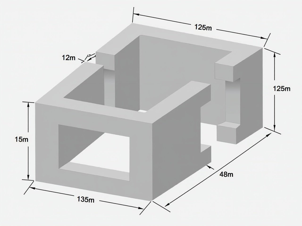
Detailed Technical Drawing of a 3D Geometric Shape with Rectangular Prisms and Dimensions
Flux Prompt

More Flux Images About A technical drawing of a complex 3D geometric shape

Detailed Technical Drawing of a 3D Geometric Shape with Rectangular Prisms and Dimensions and Related Flux Artwork

3rd angle projection showing a square with a hole of 25 radius. Dimensions are labeled around the square. The drawing is precise and technical in nature.
n

Flux AI

Technical Drawing: 3rd Angle Projection of a Square with a 25 Radius Hole

The image displays two technical drawings, which appear to represent mechanical parts or components. The left drawing showcases a profile view with several dashed and solid lines that indicate different surfaces and contours of the part. There are horizontal lines suggesting layers or levels on the part shown. The right drawing presents a front view with circular shapes that may represent holes or recesses in the material. This drawing also includes dimensions and symmetry hints, indicated by the crosshair-like symbols. Overall, the drawings convey technical specifications relevant for manufacturing or engineering analysis.
K

Flux AI

Detailed Technical Drawings of Mechanical Parts for Engineering and Manufacturing Analysis

A person is sketching a man on graph paper with a pencil.

Flux AI Image Generator

Drawing in Progress

3rd angle projection of a cylindrical object. Dimensions labeled indicate size. Clean and clear illustration for technical use.
H

FLUX.1-dev Image

Technical Drawing of Cylindrical Object in 3rd Angle Projection with Dimensions

The image presents a technical drawing of a mechanical component. It appears to have a cylindrical shape on top of a rectangular base. The dimensions are clearly marked, with various measurements indicated in millimeters. The drawing includes features such as a slot and a circular protrusion, along with dimensional indications for clarity. This could be part of a larger assembly or a specific machine part, showcasing precision engineering.
5 images
M

FLUX.1-dev Image

Technical Drawing of a Precision Mechanical Component

This image shows a technical drawing of a mechanical part designed in 3D. The component appears to be a bracket with multiple connection points and curved sections. Key dimensions are marked, indicating various radii and diameters, such as R24, R22, and several holes of different sizes. The illustration also specifies the distance between features and the overall length and height of the part. The visual style is clean, with a light blue color and clear annotations, typical for engineering schematics.
W

Flux Image Generator

Detailed Technical Drawing of a 3D Mechanical Bracket with Connection Points and Dimensions

The image displays a technical drawing of a pentagonal pyramid. It has a base with sides measuring 50 mm and an axis length of 70 mm. The base is positioned on the horizontal plane. One edge of the base is oriented perpendicularly to the vertical plane. A section plane is illustrated, which is perpendicular to the vertical plane and inclined at 40 degrees to the horizontal. This section plane bisects the pyramid's axis. The various views include the front view, sectional top view, sectional side view, and the true shape of the section, demonstrating complex geometry in a two-dimensional layout.
K

FLUX.1-dev Image

Technical Drawing of a Pentagonal Pyramid: Understanding Geometry and Sectional Views

The image presents a technical drawing of a mechanical component. It features a cylindrical shape atop a rectangular base with clearly marked dimensions in millimeters. The design includes a slot and a circular protrusion, highlighting precision in engineering. Notches are detailed along the rectangular section, and the front view shows its height of 30 units and width of 50 units. The side view captures the depth and height while emphasizing the protruding notches, making it a reliable reference for engineering and architectural projects.
p

FLUX dev AI

Precision Mechanical Component Technical Drawing with Dimensions and Notches

Create a detailed technical drawing of a mechanical component showing a base plate with rounded ends. Include a cylindrical structure with a diameter of 60 mm and a height of 60 mm on one end. Add a slot in the center of the base connecting the cylinder to a rectangular block. Label dimensions clearly.
A

FLUX dev AI

Detailed Technical Drawing of a Mechanical Component with Dimensions and Features

The image presents a technical drawing featuring a fillet with a radius of 3/4 inches. It includes precise measurements for various dimensions, including a height of 3.5 inches and width of 7 inches. The fillet is illustrated with a 37-degree angle, contributing to the drawing's overall design. The drawing is detailed, ensuring accuracy for engineering purposes. This schematic would be valuable in manufacturing or architectural contexts.
A

Flux AI

Technical Drawing of a Fillet with Dimensions and Radius Specifications

The image shows a simple illustration of a three-dimensional shape. It is a rectangular block with rounded ends, resembling a piece of machinery or a component. There are two circular holes on the rounded ends, suggesting it may be used for fastening or connection. The block has a flat bottom, indicating it is designed to sit on a surface. The drawing is in a black and white style, with minimal details, focusing on the shape itself.
G

Flux AI

Minimalist Technical Illustration of a Three-Dimensional Rectangular Block with Rounded Ends and Connection Holes

Technical drawing illustrates a pentagonal pyramid. Base measures 50 mm. Axis length is 70 mm. Base is on the horizontal plane with one edge perpendicular to the vertical plane. A section plane is shown, inclined at 40 degrees to the horizontal, bisecting the axis. The image includes front view, sectional top view, sectional side view, and true shape of the section.
P

Flux AI

Technical Drawing of Pentagonal Pyramid with Section Plane